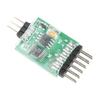
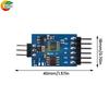
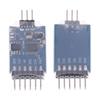
High-concerned chemical : none
Model : .
Type : Other PLC Peripheral Modules
Origin : Mainland China
Brand Name : occkic
Features
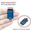
1.Support 2-channel or 3-channel video signal switching, adapt to a variety of FPV equipment and camera applications
2. Electronic switching design, fast switching speed, stable signal without delay
3.Compact module design, easy to install, suitable for drones and model airplanes.
4.High-quality video transmission, strong anti-interference ability, to ensure clear and smooth picture.
5. Adopting high-speed video switching chip, effectively reducing the vibration of video images.
Parameter:
Working Voltage: 5V±0.5V
Input Signal: Period 20ms, Pulse Width 800 microseconds to 2500 microseconds PPM Model Receiver Output Signal for Identification Signal, LED blinking (light 200ms, extinguish 3000ms), other signals are error signals, LED blinking (light 200ms, extinguish 200ms).
When low-grade PPM signal input, channel 1 is on, the other two off; high-grade PPM signal input, channel 2 is on, the other two off; medium-grade PPM signal input, channel 3 is on, the other two off.CH1 ~ CH3 each video signal channel maximum sustainable output current capacity of 100mA (Max 100mA)
Wiring Definition:
Please pay attention to the wiring order when using, the switcher itself is powered by the receiver 5V (CTL terminal), do not access the 12V video power, otherwise it will immediately burn out and can not be repaired!
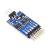
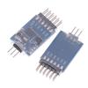
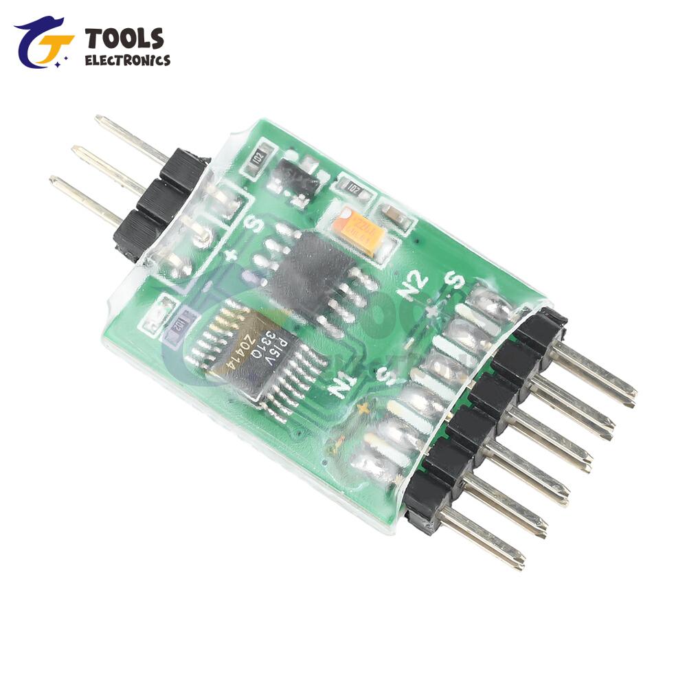
1, “S” line for the receiver's control signal line, “+” line for the product's operating voltage 5V (the receiver to provide it with 5V operating voltage), “-” line for GND.
2 CH1: Video 1 Input, connect to camera 1, “S” line is the signal input line of camera 1, “+” line is video 12V, “-” line is GND. 3. GND.
3. CH2: Video 2 Input, connect to camera 2. “S” line is the signal input line of camera 2, “+” line is video 12V, “-” line is GND. The “S” line is the signal input line of camera 2, the “+” line is for video 12V, the “-” line is for GND.
4. CH3: Video 3 Input, connect to camera 3. The ‘S’ line is the signal input line of camera 3, the “+” line is for video 12V, the “-” line is for video 12V. The “S” line is the signal input line of camera 3, the “+” line is video 12V, the “-” line is GND.
5. OUT: Video Out, connect to the AV IN port of OSD or to a picture transmitter. The “S” line is the signal output line, the “+” line is for all video 12V, the “-” line is for all video GND.
Remarks: CH1~CH3 and the four ports of OUT share the same 12V. 12V are shared, at least one of them provides 12V power for the device.
Package include
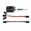
Video Switching Module*1
label:yes




 Geld zurück bei Nichtlieferung